Standard: Difference between revisions
No edit summary |
|||
| Line 15: | Line 15: | ||
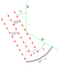
[[File:Dhkl vs elbeam.png|200px|thumb|Wave reflection on crystal lattice.]] | [[File:Dhkl vs elbeam.png|200px|thumb|Wave reflection on crystal lattice.]] | ||
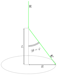
[[File:Elbeam and ring for crystals.png |200px|thumb|Scheme of diffraction experiment on a polycrystalline target.]] | [[File:Elbeam and ring for crystals.png |200px|thumb|Scheme of diffraction experiment on a polycrystalline target.]] | ||
The most widely used in GED polycrystalline standard is the zinc oxide ZnO. Several reasons are behind its' prevalence. | |||
* It is inexpensive and simple to prepare. The metallic Zn burned to yield ZnO in form of smoke which is condensed on the wire net substrate. | |||
* It has only one stable crystal modification at conditions of GED experiments. | |||
==== Theoretical considerations ==== | ==== Theoretical considerations ==== | ||
==== Bragg- | ==== Bragg-Wulff equation ==== | ||
The scattering on the polycrystalline sample can be described with the Bragg- | The scattering on the polycrystalline sample can be described with the Bragg-Wulff equation: | ||
<math> | <math> | ||
| Line 23: | Line 28: | ||
</math> | </math> | ||
where | where hkl — are Miller indices, ''d''<sub>hkl</sub> is the distance between hkl crystallographic planes, ''θ'' — is the reflection angle from the corresponding plane, ''n'' — is the positive integer. The GED usually operates with the scattering angle ''φ''. The relationship between ''θ'' and ''φ'' is <math>\varphi=2\theta</math> (see Figures). As it can be easily seen from the illustration <math>\varphi=\arctan( \frac{R}{L} )</math>, where ''R'' is the ring radius, ''L'' is the nozzle-to-detector distance. Therefore the substitution of the scattering angle ''φ'' into the Bragg-Wulff formula results in the equation for the wavelength determination: | ||
<math> | <math> | ||
\lambda = \frac{2d_{hkl}}{n}\sin (\frac{1}{2} \arctan ( \frac{R}{L} ) ) . | \lambda = \frac{2d_{hkl}}{n}\sin (\frac{1}{2} \arctan ( \frac{R}{L} ) ) . | ||
</math> | </math> | ||
In real electron diffraction experiments only rings for ''n'' = 1 are observed. | |||
==== Calculation of the interplane distance ==== | ==== Calculation of the interplane distance ==== | ||
The distances between the cystallographic planes can be calculated from the lattice parameters: | The distances between the cystallographic planes can be calculated from the lattice parameters: | ||
| Line 39: | Line 47: | ||
2 \frac{kl}{bc}(\cos\beta \cdot \cos\gamma - \cos\alpha) ], | 2 \frac{kl}{bc}(\cos\beta \cdot \cos\gamma - \cos\alpha) ], | ||
</math> | </math> | ||
where <math>s= 1 - \cos^2 \alpha - \cos^2 \beta - \cos^2 \gamma + 2 \cos\alpha \cos\beta \cos\gamma </math>. | where <math>s= 1 - \cos^2 \alpha - \cos^2 \beta - \cos^2 \gamma + 2 \cos\alpha \cos\beta \cos\gamma </math>. | ||
This formula is easily simplified to smaller equations for the cases of lattices more symmetrical then the triclinic one. | This formula is easily simplified to smaller equations for the cases of lattices more symmetrical then the triclinic one. | ||
| Line 46: | Line 55: | ||
\frac{1}{d_{hkl}^2} = \frac{4}{3}\frac{h^2+hk+k^2}{a^2} + \frac{l^2}{c^2} . | \frac{1}{d_{hkl}^2} = \frac{4}{3}\frac{h^2+hk+k^2}{a^2} + \frac{l^2}{c^2} . | ||
</math> | </math> | ||
Revision as of 17:17, 8 October 2015
Standards in GED
Standards are used in GED for calibration of electron wavelength or nozzle position. There are two kinds of them:
| Type of standard | Examples |
|---|---|
| Gas | C6H6, CCl4, CO2, CS2 |
| Polycrystalline | ZnO, TlCl |
Polycrystalline standards
The most widely used in GED polycrystalline standard is the zinc oxide ZnO. Several reasons are behind its' prevalence.
- It is inexpensive and simple to prepare. The metallic Zn burned to yield ZnO in form of smoke which is condensed on the wire net substrate.
- It has only one stable crystal modification at conditions of GED experiments.
Theoretical considerations
Bragg-Wulff equation
The scattering on the polycrystalline sample can be described with the Bragg-Wulff equation:
<math> 2d_{hkl} \sin \theta = n \lambda , </math>
where hkl — are Miller indices, dhkl is the distance between hkl crystallographic planes, θ — is the reflection angle from the corresponding plane, n — is the positive integer. The GED usually operates with the scattering angle φ. The relationship between θ and φ is <math>\varphi=2\theta</math> (see Figures). As it can be easily seen from the illustration <math>\varphi=\arctan( \frac{R}{L} )</math>, where R is the ring radius, L is the nozzle-to-detector distance. Therefore the substitution of the scattering angle φ into the Bragg-Wulff formula results in the equation for the wavelength determination:
<math> \lambda = \frac{2d_{hkl}}{n}\sin (\frac{1}{2} \arctan ( \frac{R}{L} ) ) . </math>
In real electron diffraction experiments only rings for n = 1 are observed.
Calculation of the interplane distance
The distances between the cystallographic planes can be calculated from the lattice parameters:
- unit cell edges lengths a, b, c,
- angles between edges α, β, γ.
The general formula is:
<math> \frac{1}{d_{hkl}^2} = \frac{1}{s} [ (\frac{h\sin\alpha}{a})^2 + (\frac{k\sin\beta}{b})^2 +\\ + (\frac{l\sin\gamma}{c})^2 + 2 \frac{hk}{ab}(\cos\alpha \cdot \cos\beta - \cos\gamma) + 2 \frac{hl}{ac}(\cos\alpha \cdot \cos\gamma - \cos\beta) + 2 \frac{kl}{bc}(\cos\beta \cdot \cos\gamma - \cos\alpha) ], </math>
where <math>s= 1 - \cos^2 \alpha - \cos^2 \beta - \cos^2 \gamma + 2 \cos\alpha \cos\beta \cos\gamma </math>. This formula is easily simplified to smaller equations for the cases of lattices more symmetrical then the triclinic one. For example, in the case of hexagonal lattice, where <math>a=b\neq c</math>, <math>\alpha=\beta=90^{\circ}</math>, <math>\gamma = 120^{\circ}</math> the equation for dhkl would be:
<math> \frac{1}{d_{hkl}^2} = \frac{4}{3}\frac{h^2+hk+k^2}{a^2} + \frac{l^2}{c^2} . </math>

